T410 Sicherungen: Unterschied zwischen den Versionen
Aus ThinkPad-Wiki
Jal2 (Diskussion | Beiträge) |
Jal2 (Diskussion | Beiträge) Keine Bearbeitungszusammenfassung |
||
| Zeile 18: | Zeile 18: | ||
{| class="wikitable" | {| class="wikitable" | ||
|- | |- | ||
! | ! Name !! Current !! Part Number !! Page !! Function | ||
|- | |- | ||
| F1 || 1.5A || ERBSD1R50U || 51 || Modem, 3.3V to pin 6 | | F1 || 1.5A || ERBSD1R50U || 51 || Modem, 3.3V to pin 6 | ||
| Zeile 44: | Zeile 44: | ||
| F12 || 10A || 458010 || 76 || power from primary battery | | F12 || 10A || 458010 || 76 || power from primary battery | ||
|- | |- | ||
| F13 || 1A || ERBSD1R00U || 66 || 5V power supply for trackpoint | | F13 || 1A || ERBSD1R00U || 66 || 5V power supply for trackpoint or LED in keyboard (?) | ||
|- | |- | ||
| F14 || 0.5A || ERBSD0R50U || 25 || power supply for microphone (in the display unit) | | F14 || 0.5A || ERBSD0R50U || 25 || power supply for microphone (in the display unit) | ||
| Zeile 50: | Zeile 50: | ||
| F15 || 0.5A || ERBSD0R50U || 67 || Touchpad, Bluetooth or Fingerprint power supply | | F15 || 0.5A || ERBSD0R50U || 67 || Touchpad, Bluetooth or Fingerprint power supply | ||
|- | |- | ||
| F16 || 0 | | F16 || 0.5A || ERBSD0R50U || 25 || Status LED or Camera power supply (3.3V to display unit) | ||
|- | |- | ||
| | | F17 || 0.5A || ERBSD0R50U || 67 || Touchpad, Bluetooth or Fingerprint power supply (most probably BT) | ||
|- | |||
| F18 || - || NANOSMDC150F || 28 || Polyfuse for 3.3V Pin on Display Port (not marked in pictures above) | |||
|- | |||
| F19 || 0.5A || ERBSD0R50U || 25 || 3.3V to EDID EEPROM in LCD | |||
|- | |||
| F20 || 0.5A || ERBSD0R50U || 76 || EC power supply from DC-In on docking station | |||
|- | |||
| F21 || 1A || ERBSD1R00U || 66 || 3.3V power supply for LED in keyboard and/or trackpoint (?) | |||
|- | |||
| F22 || - || NANOSMDC150F || 27 || 5V to pin of VGA connector (polyfuse) | |||
|} | |} | ||
Version vom 30. September 2014, 20:26 Uhr
Fuses in the T410 (nVidia)
Location on the Planar
These pictures show the locations of the fuses on a mainboard FRU 63Y1523.
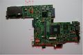
T410 Mainboard Top Side
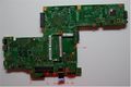
T410 Mainboard Bottom Side


--Jal2 (Diskussion) 21:42, 30. Sep. 2014 (CEST)
Specs and Function
Column Page refers to the page of the schematics called "NOZOMI-1 EXT SDV LOGIC SCHEMATICS. NZM1H-1 VER 1.31 DEC/04/2008". Part Number and nominal current are taken from this schematics, too.
| Name | Current | Part Number | Page | Function |
|---|---|---|---|---|
| F1 | 1.5A | ERBSD1R50U | 51 | Modem, 3.3V to pin 6 |
| F2 | 7A | 429007 | 75 | DC-In |
| F3 | 3A | ERBSD3R00U | 25 | LCD Panel Circuit |
| F4 | 2A | ERBSD2R00U | 69 | Fan Control |
| F5 | 0.5A | ERBSD0R50U | 76 | EC power supply from DC-In |
| F6 | 0.5A | ERBSD0R50U | 67 | Touchpad, Bluetooth or Fingerprint power supply |
| F7 | 3A | ERBSD3R00U | 25 | LCD Backlight |
| F8 | 0.5A | ERBSD0R50U | 25 | Status LED or Camera power supply (3.3V to display unit) |
| F9 | 0.5A | ERBSD0R50U | 76 | EC power supply from main battery |
| F10 | 0.5A | ERBSD0R50U | 76 | EC power supply from secondary batery (slice) |
| F11 | 10A | 458010 | 76 | power from secondary battery (slice) |
| F12 | 10A | 458010 | 76 | power from primary battery |
| F13 | 1A | ERBSD1R00U | 66 | 5V power supply for trackpoint or LED in keyboard (?) |
| F14 | 0.5A | ERBSD0R50U | 25 | power supply for microphone (in the display unit) |
| F15 | 0.5A | ERBSD0R50U | 67 | Touchpad, Bluetooth or Fingerprint power supply |
| F16 | 0.5A | ERBSD0R50U | 25 | Status LED or Camera power supply (3.3V to display unit) |
| F17 | 0.5A | ERBSD0R50U | 67 | Touchpad, Bluetooth or Fingerprint power supply (most probably BT) |
| F18 | - | NANOSMDC150F | 28 | Polyfuse for 3.3V Pin on Display Port (not marked in pictures above) |
| F19 | 0.5A | ERBSD0R50U | 25 | 3.3V to EDID EEPROM in LCD |
| F20 | 0.5A | ERBSD0R50U | 76 | EC power supply from DC-In on docking station |
| F21 | 1A | ERBSD1R00U | 66 | 3.3V power supply for LED in keyboard and/or trackpoint (?) |
| F22 | - | NANOSMDC150F | 27 | 5V to pin of VGA connector (polyfuse) |