UEFI BIOS T420 BIOS Structure: Unterschied zwischen den Versionen
Jal2 (Diskussion | Beiträge) |
Jal2 (Diskussion | Beiträge) |
||
| Zeile 29: | Zeile 29: | ||
|} | |} | ||
The procedure below was tested with both T420 und T520 and it will probably also be applicable with X220 and W520. | |||
=== Structure of a .FL1 File === | === Structure of a .FL1 File === | ||
| Zeile 40: | Zeile 42: | ||
GUIDs match the ones retrieved from the SPI flash. | GUIDs match the ones retrieved from the SPI flash. | ||
Therefore | Therefore we can update the whole BIOS in the T420 SPI flash by writing 3MByte starting at flash offset 0x500000. | ||
=== Connect a RaspberryPi to a T420/T520 === | |||
This is similar to the [http://thinkwiki.de/UEFI_BIOS_Update_with_a_Raspberry_Pi#Attach_the_Raspberry_PI_to_the_SPI_Flash S430]. Only difference is, that | |||
in the T420/T520 all regions (IntelME, GbE, BIOS and descriptor table) reside in one 8MByte SPI Flash. | |||
=== Flash Access with flashrom === | |||
* Take the *.FL1 file from the official Lenovo BIOS Update, e.g. $01C9100.FL1, and truncate it to exactly 8MByte: | |||
'''dd if=\$01C9100.FL1 of=t520_spi.bin bs=$((0x800000)) count=1''' | |||
* Copy this file to the RaspberryPi, e.g. using scp. | |||
* Backup the old content. This may take some minutes: | |||
'''flashrom -p linux_spi:dev=/dev/spidev0.0 -r t520_old.bin''' | |||
* You may need to tell the tool which flash IC it is with the "-c" option: | |||
'''flashrom -p linux_spi:dev=/dev/spidev0.0 -c MX25L6405 -r t520_old.bin''' | |||
''' | * Repeat the backup with another filename and compare the content of both files. If they don't match, do this a third time. | ||
'''flashrom -p linux_spi:dev=/dev/spidev0.0 -r t520_oldB.bin''' | |||
'''md5sum old_bios*.bin''' | |||
and | * If you still get different files, re-check the cabling and re-connect the Ponoma chip to the flash chip. | ||
''' | * As we want to write only the BIOS part in the SPI flash starting at offset 0x500000, we need a layout file: | ||
'''echo -e "000000:4fffff dummy\n500000:7fffff bios" > t520.layout''' | |||
* Update the BIOS portion in the SPI flash: | |||
'''flashrom -p linux_spi:dev=/dev/spidev0.0 --layout t520.layout -i bios -w t520_spi.bin''' | |||
[[Category:BIOS]] | [[Category:BIOS]] | ||
Version vom 8. Mai 2016, 19:45 Uhr
T420 SPI Flash Structure
It seems like the T420 BIOS update file (.FL1) is not an UEFI capsule as found for the Edge S430.
This page describes work in progress.
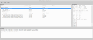
Structure of a Dump of the T420 SPI Flash
This is the output of the UEFITool for a dump of a T420 SPI Flash:
The SPI flash of the T420 has a size of 8MByte with this structure:
| Offset | Length | Description |
|---|---|---|
| 0x0 | 0x1000 | descriptor region |
| 0x1000 | 0x2000 | GbE region |
| 0x3000 | 0x4fd000 | Intel ME region |
| 0x500000 | 0x300000 | BIOS region |
The procedure below was tested with both T420 und T520 and it will probably also be applicable with X220 and W520.
Structure of a .FL1 File
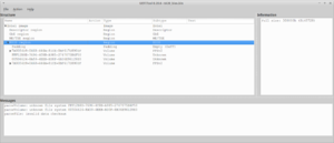
This file was taken from the Windows BIOS Update for version 1.37 (83ET67WW) of the T420.
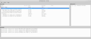
The padding of 0x520000 bytes matches the offset of the BIOS part in the flash (0x500000) plus the padding area at the start of the flash (0x20000). The following four volumes, up to and including the volume with the GUID 7A9354D9-0468-444A-81CE-0BF617D890DF, have a combined size of 0x2E0000. Their GUIDs match the ones retrieved from the SPI flash.
Therefore we can update the whole BIOS in the T420 SPI flash by writing 3MByte starting at flash offset 0x500000.
Connect a RaspberryPi to a T420/T520
This is similar to the S430. Only difference is, that in the T420/T520 all regions (IntelME, GbE, BIOS and descriptor table) reside in one 8MByte SPI Flash.
Flash Access with flashrom
- Take the *.FL1 file from the official Lenovo BIOS Update, e.g. $01C9100.FL1, and truncate it to exactly 8MByte:
dd if=\$01C9100.FL1 of=t520_spi.bin bs=$((0x800000)) count=1
- Copy this file to the RaspberryPi, e.g. using scp.
- Backup the old content. This may take some minutes:
flashrom -p linux_spi:dev=/dev/spidev0.0 -r t520_old.bin
- You may need to tell the tool which flash IC it is with the "-c" option:
flashrom -p linux_spi:dev=/dev/spidev0.0 -c MX25L6405 -r t520_old.bin
- Repeat the backup with another filename and compare the content of both files. If they don't match, do this a third time.
flashrom -p linux_spi:dev=/dev/spidev0.0 -r t520_oldB.bin md5sum old_bios*.bin
- If you still get different files, re-check the cabling and re-connect the Ponoma chip to the flash chip.
- As we want to write only the BIOS part in the SPI flash starting at offset 0x500000, we need a layout file:
echo -e "000000:4fffff dummy\n500000:7fffff bios" > t520.layout
- Update the BIOS portion in the SPI flash:
flashrom -p linux_spi:dev=/dev/spidev0.0 --layout t520.layout -i bios -w t520_spi.bin


